
Sink marks, warpage, weld lines, burn marks and short shots are the most common defects in plastic injection molding. They almost always arise from how the material fills the mold, is packed and cools: this is why Moldflow simulation can predict them and find their cause, before the mold is built or on a mold already in production.
Below are the most common defects, their causes and how we deal with them, with links to real cases.
Sink marks and voids
Causes: in thick areas the core of the part stays hot longer and, as it shrinks, pulls the surface inwards. The defect gets worse if packing is insufficient or if the gate freezes before the thick area has been compensated.
What simulation shows: the areas with a high probability of sink marks, volumetric shrinkage and gate freezing. Wall thicknesses, gate position and size and the packing profile are evaluated.

Read more: Sink index · Volumetric shrinkage · Gate sizing · Cover
Warpage
Causes: the part shrinks differently from area to area. The causes are thickness differences, non-uniform cooling between the two mold halves and, in filled materials, fiber orientation.
What simulation shows: the warpage of the part and the share due to each cause. This shows whether to act on cooling, gate positions or geometry.

Read more: Deflection · Fiber orientation · Cooling · Motorcycle Helmet · Mirror Bracket
Weld lines
Causes: two flow fronts meet, for example around a hole or with several gates. The line is more visible and weaker when the fronts meet cold or at an unfavourable angle.
What simulation shows: where weld lines form and at what temperature. It shows whether moving the gate or changing wall thicknesses moves the line to a less critical area.

Read more: Weld lines · Simulation vs Reality · Mirror Bracket
Burn marks and air traps
Causes: air is trapped between flow fronts or at the end of the cavity and, compressed quickly, heats up until it burns the material. High injection velocities and missing or badly placed vents make it worse.
What simulation shows: the areas where air is trapped, and therefore where to place vents or how to change filling.

Read more: Air traps · Automotive Part · Shower Tube
Short shots, hesitation and imbalance
Causes: the material stops or slows down in thin areas and cools before filling them; in multi-cavity or family molds, some cavities fill before the others.
What simulation shows: how the flow front advances over time, hesitation areas and the balance between cavities. Runners are sized to balance filling.
Read more: Fill time · Filling balance · Simulation vs Reality · Shower Tube
Flash
Causes: material escapes at the parting line when cavity pressure exceeds the clamping force of the machine, or with excessive holding pressure and worn molds.
What simulation shows: pressures in the mold and the clamp force needed at every instant, to choose the machine and the packing profile.

Read more: Clamp force · Packing · Shower Tube
Dull areas, surface marks and degradation
Causes: velocity changes during filling, gates that are too small and excessive shear, which can also degrade the material.
What simulation shows: shear rate and shear stress, compared with the material limits. For surface defects, simulation is combined with targeted trials at the press.
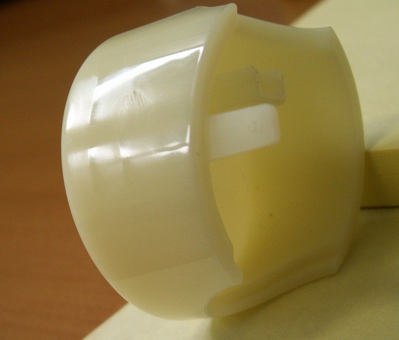
Read more: Shear rate · Surface Dullness · Shower Tube
How we work
If the part is still being designed, simulation is used to choose gates, runners, cooling and process parameters before the mold is built. If the defect is already present in production, we reproduce the real conditions in simulation, compare the results with the molded parts and check the possible solutions before modifying the mold.