How far can a simulation be trusted? In this study, on a glass-filled polyamide technical part already in production, the filling calculated with Moldflow was compared step by step with real short shots, taken from the mold at different filling levels. Final goal: to find out whether a weld line in a critical area of the part could be moved.
1. Preliminary geometry check
As a first step, the actual wall thicknesses of the part were compared with those of the 3D CAD model: differences were in the order of 0.1–0.2 mm, therefore negligible for the simulation. To describe the many details of the part accurately a very fine mesh was used, optimised for the filling phase only.
Process parameters used, the same as in production: mold temperature 100 °C, melt temperature 300 °C, injection time 3.2 s, velocity/pressure switch-over at 97% of volume.
2. Simulation compared with short shots
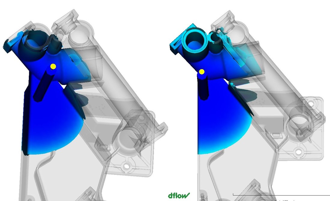
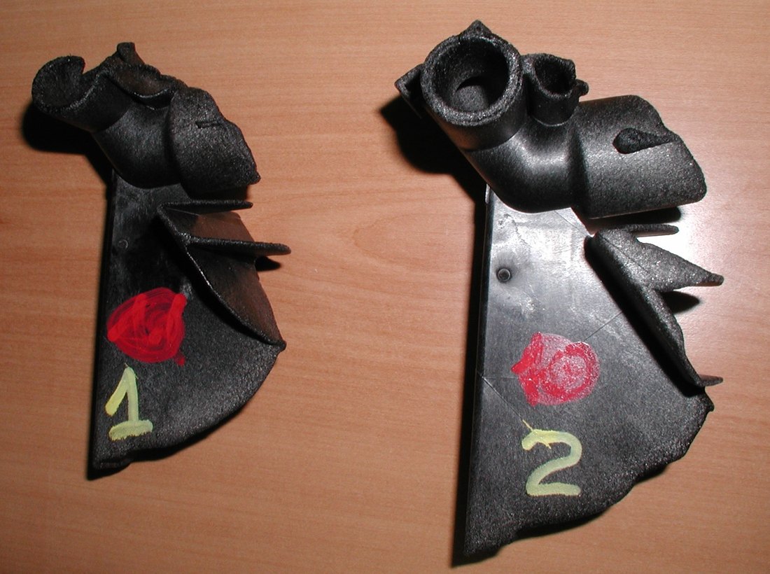
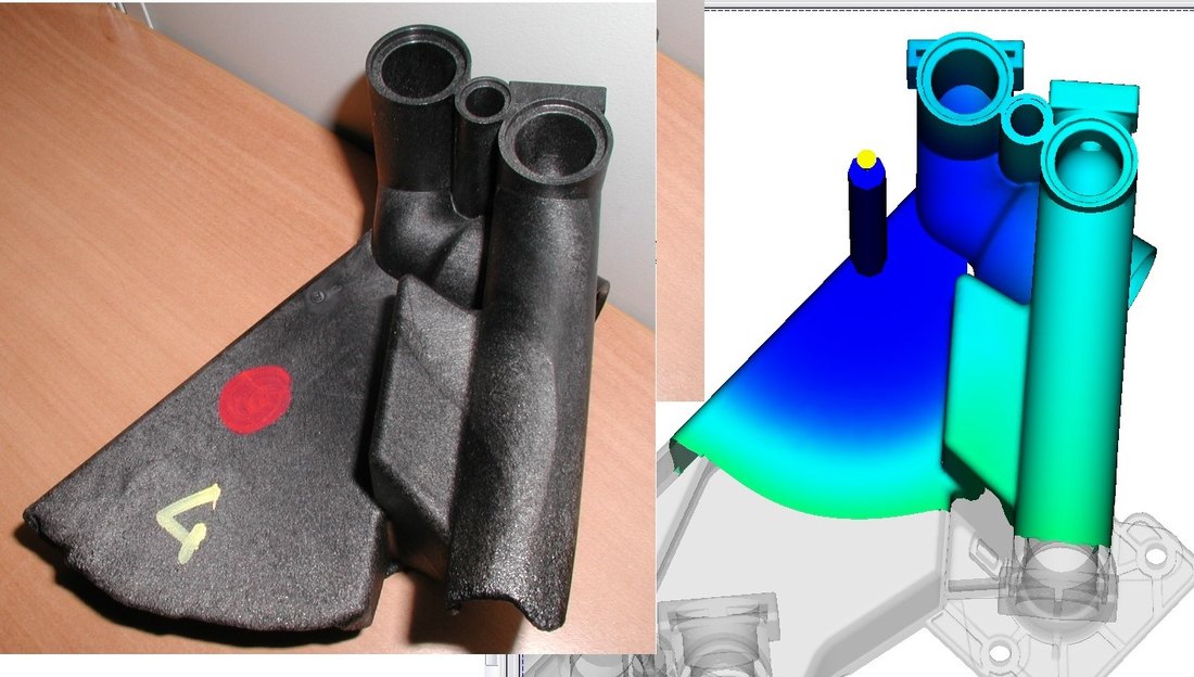
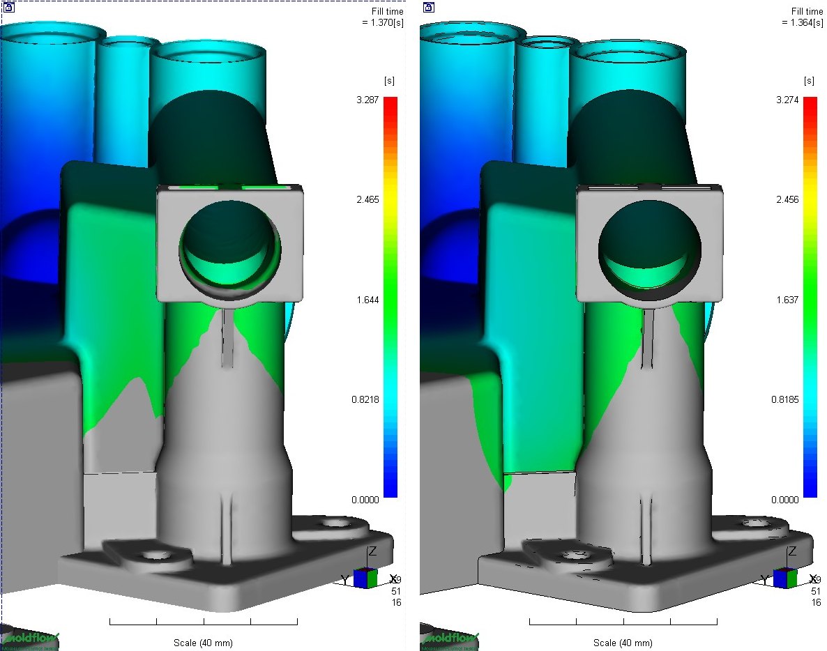
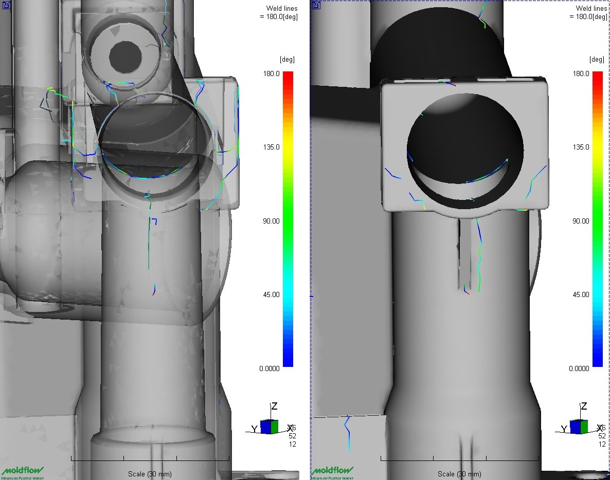
The weld line position depends on the upper cylindrical part of the piece and on a thick rib: the material preferably advances where the wall is thicker and, flowing down the cylinder, creates the weld line. The simulation also shows the different flow front priorities inside the part.
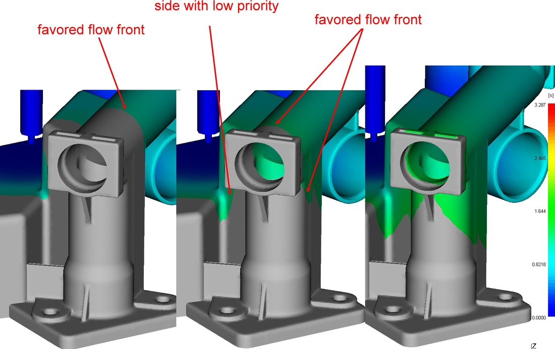
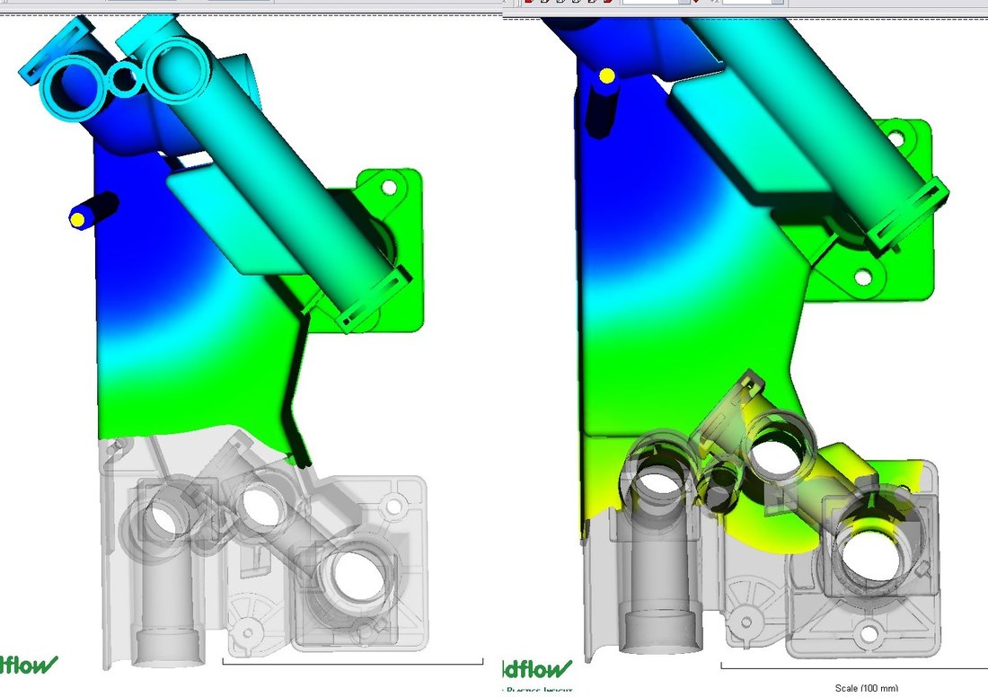
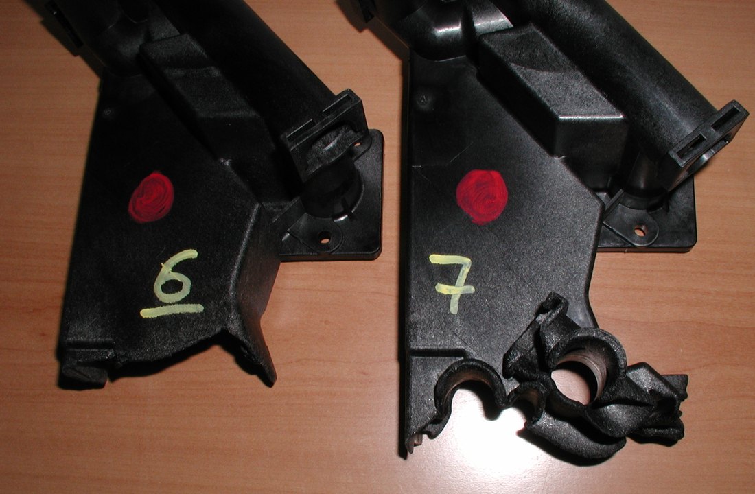
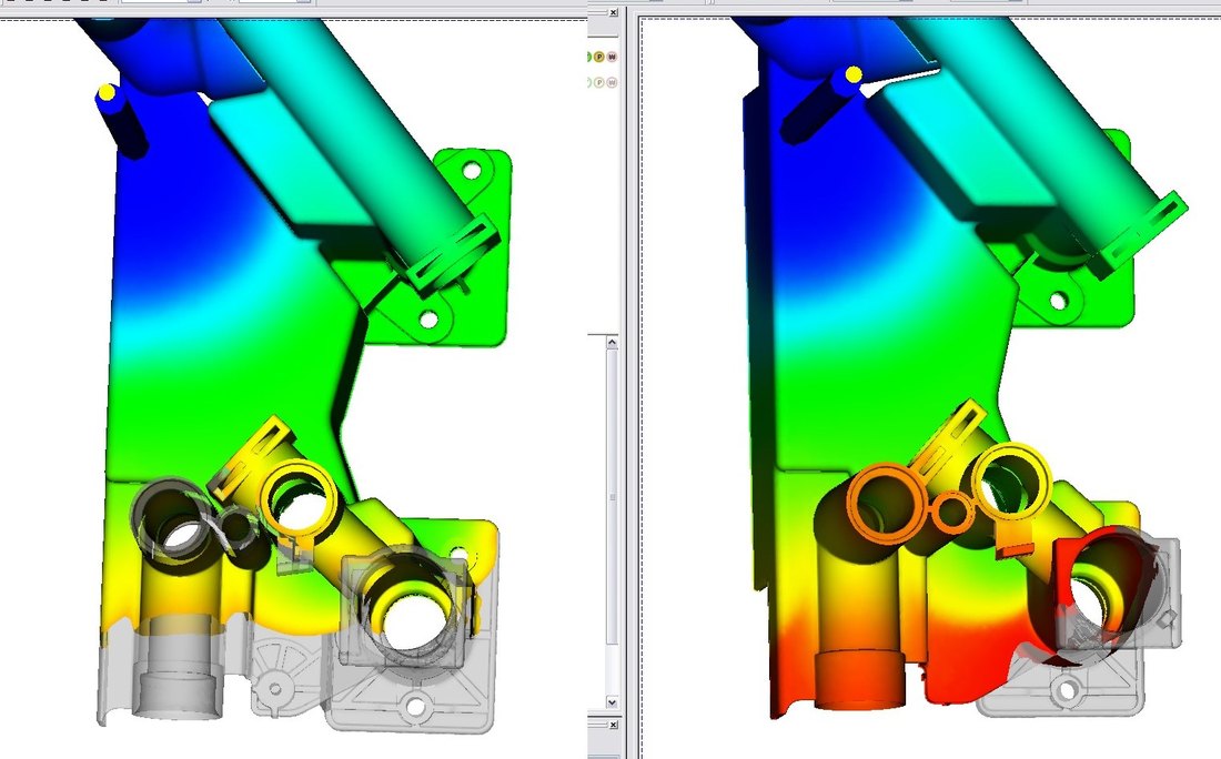
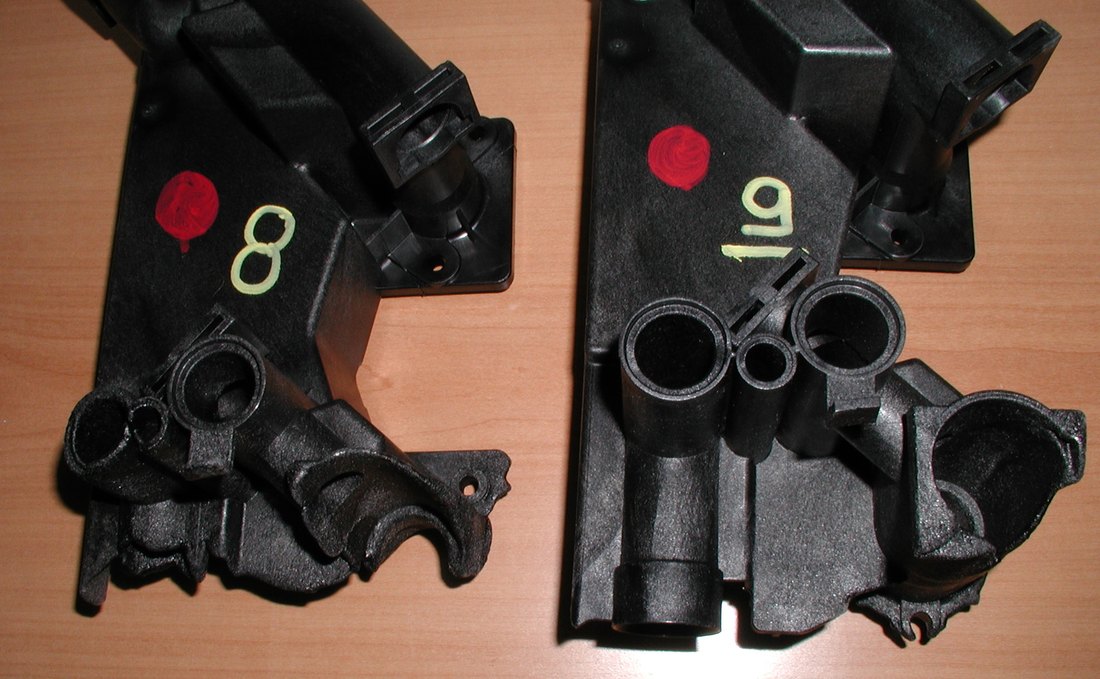
In all compared steps the match between simulation and real short shots was very high: the model was therefore considered validated and used to evaluate changes to the part.
3. Can the weld line be moved?
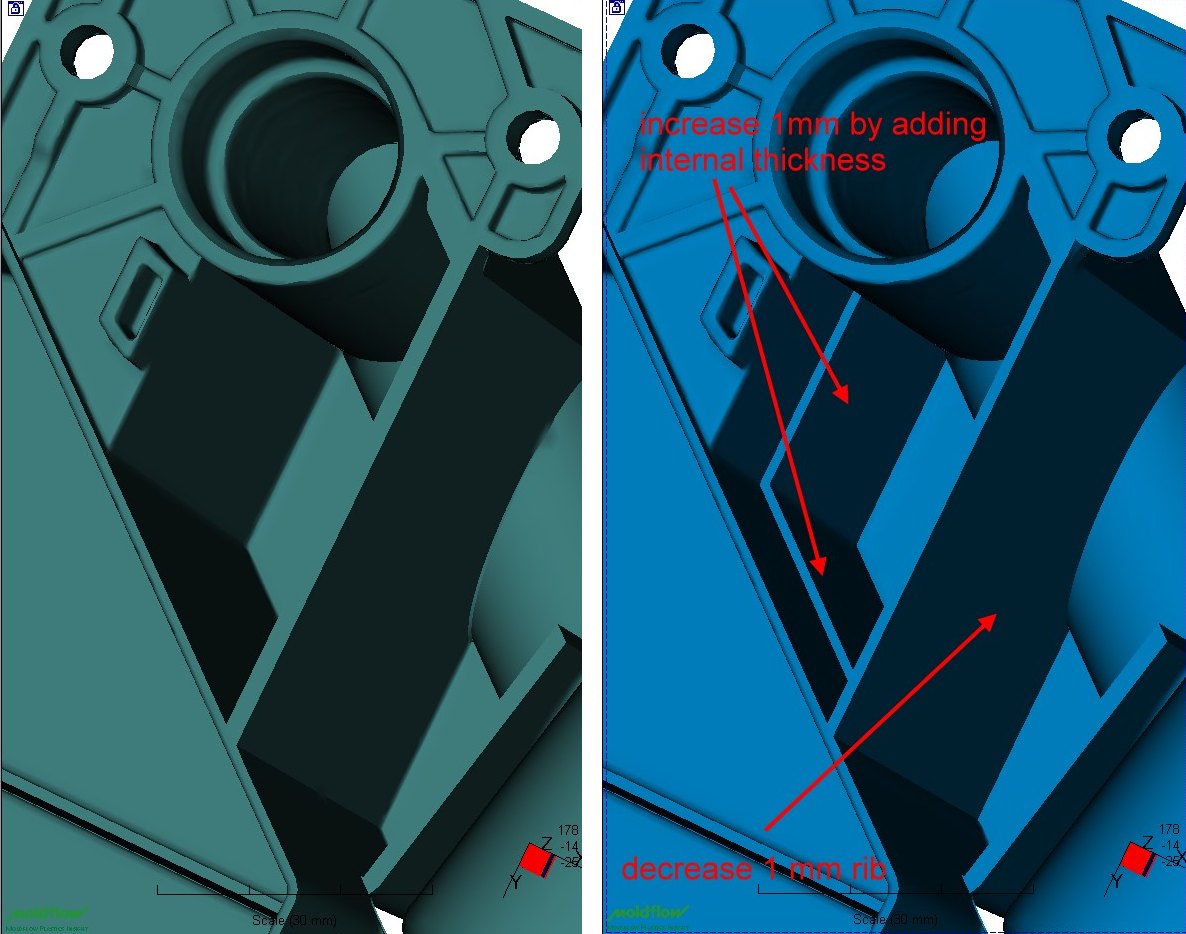
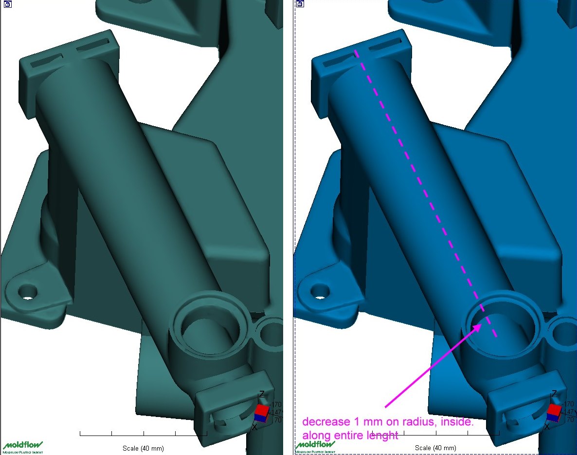
First variant: +1 mm wall thickness inside the part, to ease material flow, and reduced thickness at the top of the cylinder, to delay the flow front there. Filling remains very similar to the original and the weld line does not move.
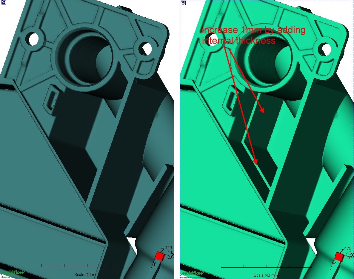
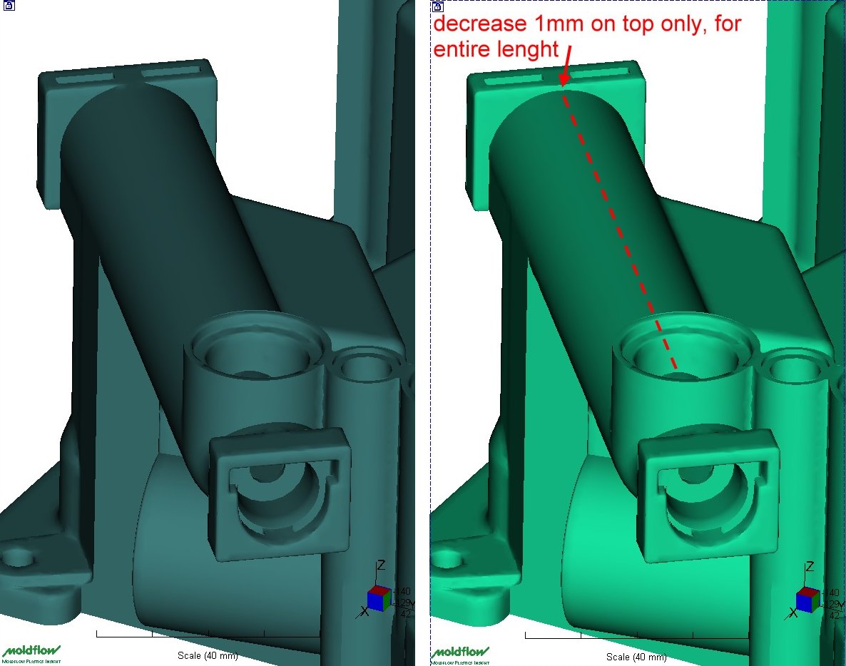
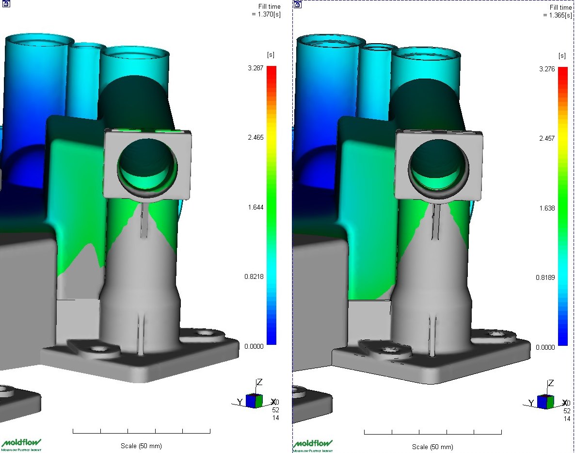
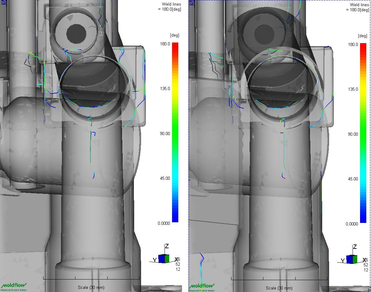
Second variant: in addition to the increased internal thickness, a thinner rib to the right of the weld line and reduced thickness on the whole upper cylindrical part. The weld line moves, but only by a few millimetres: with such a high-flow material small geometry changes have little effect on filling.
The result: practical advice
The study showed that the weld line cannot be moved without drastic changes to the part or a change of injection point, at much higher cost. Moreover, the weld line forms with high-temperature material: the part has other weld lines, formed at lower temperature, that cause no problems in service. The failure therefore does not depend on the weld line alone.
The advice given to the customer was to reinforce the failure area rather than move the weld line: two ribs along the circumference, perpendicular to the weld line, and a rib inside the cylinder parallel to it, so as to bring the weld line itself inside the rib.